
PLC or Programmable Logic Controller is a computer designed to operate under harsh industrial conditions like wet, dry, extreme temperature, or dusty conditions. Programmable Logic Controllers are used to automate a lot of industrial processes like assembly lines of manufacturing plants, ore processing plants, or wastewater treatment facilities.
This technology shares a lot of features and functionalities of personal computers people have at home. Both PLC and personal computers have a Central Processing Unit, power supply, Operating System Software (although different software), memory, and inputs and outputs.
The most significant difference is that automated logic controls can perform continuous and discrete functions that a personal computer cannot do, and PLCs are better suited to extreme and rough industrial conditions. It can be thought of as a “ruggedized” computer that manages electromechanical processes of industrial environments.
This technology plays a vital role in the field of automation and uses form part of a larger Supervisory Control and Data Acquisition system to operate. It can be programmed according to the requirement of processes. Especially in the manufacturing industry, there will always a need for reprogramming because of the changes in the industry’s nature of production.
To overcome the problem, PLC-based systems were introduced. We will first take a closer look at the basics of Programmable Logic Controller before looking at various PLCs apps. If people want to learn how to program a Programmable Logic Controller, they need to check out some of the different PLC training courses found on the Internet. These courses can help people to jumpstart their careers in the engineering industry.
The basics of PLC
This technology was invented in 1964 by Dick Morley. Since then, it has revolutionized the manufacturing and industrial sectors. There’s a wide range of automated control functions like counting, comparing, timing, processing, and calculating various analog signals. The primary advantage of this technology over hard-wired control systems is that companies can go back and change it after you have programmed it, at least cost.
Check out this site for more details about hard-wired control system.
In hard-wired control systems, companies usually have to rip out tons of wires and start from the bottom, which is a lot more expensive and will take a look longer. Imagine having a light connected to the switch. Usually, the light will operate under certain conditions – that it is either ON or OFF. Now you are tasked that when turning the switch ON, the light needs to glow only after half a minute.
With this type of setup, you are now stuck. The only way you can achieve this is to rewire the whole circuit and add a timing relay mechanism. That is a lot of unnecessary tasks for a small change. It is where PLC comes into play, which does not require additional hardware and wiring to make sure of the changes.
Instead, it requires simple code changes, programming the system to only turn on the light for half a minute after turning ON the switch. That is why, by using PLC, it is a lot easier to incorporate multiple outputs and inputs. It is just a simple example. A programmable Logic Controller can control more complex and more extensive processes. It can be customized depending on the apps and the need of users.
How does it work?
The working of a PLC can be understood as a cyclic scanning technique known as scan cycles. A scan process includes the steps listed below:
The Operating System or OS starts monitoring and cycling of time.
The Central Processing Unit starts reading pieces of information from the input module, as well as checks the status of the inputs.
The Central Processing Unit starts executing application or user programs written in relay-LL (ladder logic) or any PLC-programming languages.
Next, the Central Processing unit performs communication and internal diagnosis tasks.
According to program results, it writes information into the output module so that every output is updated. This process will continue as long as the system is in run mode.
For more information about this subject, visit websites like https://onlineplcsupport.com for more info.
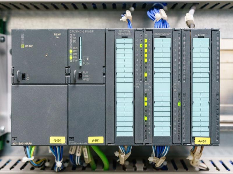
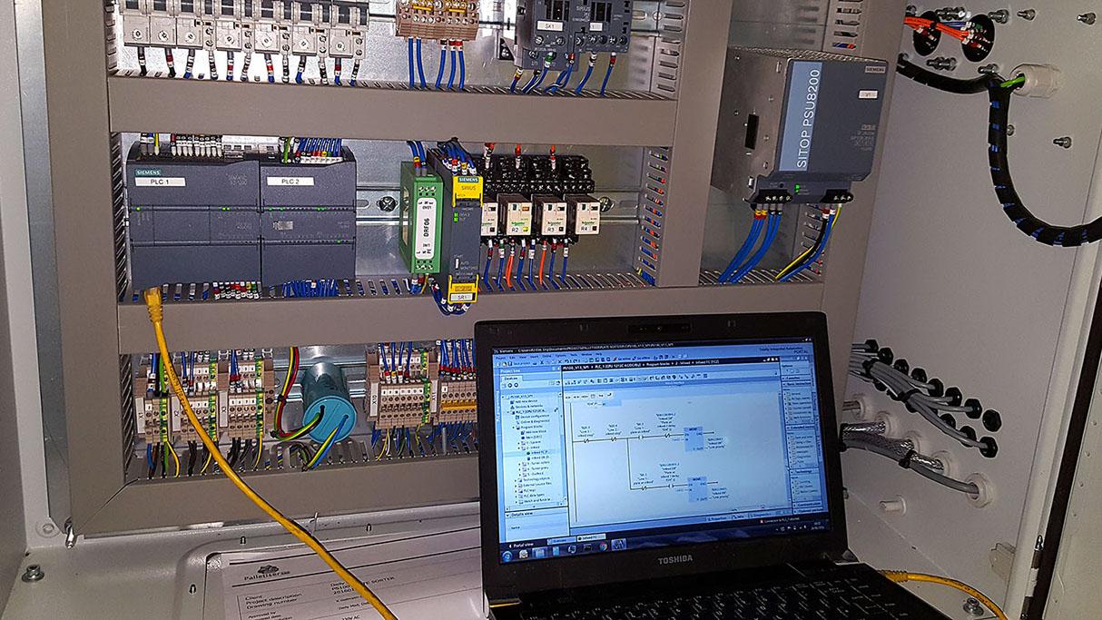
Structure of PLCs
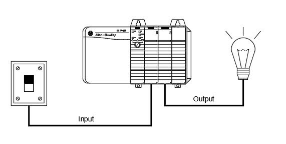
The physical structure of this technology is almost the same as the personal computer’s structure. PLCs continuously monitors input values from different input sensing devices like a weight scale, accelerometer, or hard-wired signals and produce a corresponding output depending on industry and production nature. A conventional block diagram of a Programmable Logic Controller consists of parts, namely:
Chassis or Rack
Communication Interface Module
CPU or Central Processing Unit
Power Supply and I/O Module
Chassis or Rack
In all Programmable Logic Controller systems, the chassis or rack form the most vital module and acts as the system’s backbone. It is available in different sizes and shapes. When a complex control system is involved, it will require a larger rack or chassis.
A small-sized controller is equipped with fixed Input and Output pin configurations. That is why they have gone for a modular type rack system, which accepts various types of Input and Output modules with the fit and sliding in concepts. All Input and Output modules will be stored inside the chassis or rack.
Power Supply Module
These modules are used to provide the necessary power to the whole system. It converts the available Alternating Current power to Direct Current power, which is required by the Input and Output, as well as the Central Processing Unit module. This technology usually works on a 24-Voltage Direct Current supply. Few automated control systems use an isolated power supply.
Memory and CPU module
CPUs have a central processor, RAM, and ROM memory. ROM includes an operating system, app programs, and drivers. RAM is used to store information and programs. The CPUs are the brain of the system with a hexagonal or octal microprocessor. Being a CPU that uses microprocessors, it replaces relays, counters, and timers. As single bits or word processors, two types of processors can be incorporated using an automated controller.
One-bit processor is used to help perform ladder logic functions. At the same time, word processors are being used to process numerical information, text, recording information, and control. The Central Processing Unit reads the input information from sensors, processes the data, and sends it to the controlling devices using various commands. The direct Current power source is the needed voltage signals. The CPU also contains electrical parts that help connect cables used by other systems.
I/O module
Input devices can stop and start switches, pushbuttons, and other devices, and output devices can be a valve, electrical heater, or relays. Input and Output modules can help interface input and output devices that are using microprocessors.


More Stories
IEEE Computer Society
Kementerian Komunikasi Dan Informatika
Latest Smartphones, Tech Offers Right this moment, New Cellular Telephones Launch, Gadgets Information, Latest Tech News India